Voltage drop across wire
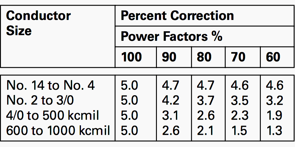
Experiment with an electronics kit. F is the factor we get from the standard table below.

How To Calculate Voltage Drop For Long Paired Wire Runs
V 9 10 90 V.
. During charging of the capacitor. From one end of a copper wire or cable to the other expect a voltage drop of 02 volts or less. Find the voltage drop across the circuit.
If a circuit containing a voltage source is broken the full voltage of that source will appear across the points of the break. Voltage drop across a resistor. The current and voltage across R 1 produce power which is dissipated in the form of heat.
It is also relative between two points. 1130 130 15. V_R1 V_R2 V_A V_B.
The two parallel 30 ohm resistors have an equivalent resistance of 15 ohms. Voltage Drop Testing. A 20 copper wire and a 40 aluminum wire can maintain less than a 3 voltage drop over 50 feet.
020 V across a wire or cable 030 V across a switch 010 V at a ground. When the capacitor isnt charged. Through a circuit a current of 12A flows through that carries a resistance of 20 Ω.
The National Electrical Code states that the voltage drop of a feeder circuit must not exceed 5 and the voltage drop of a branch circuit must not exceed 3. This voltage drop level is. View the circuit as a schematic diagram or switch to a lifelike view.
Hence the wire length concept. Voltage drop is one of the most common electrical problems showing up in automotive shops today. The total resistance appears as 75 ohms to the 150v source.
For example an electric space heater may have a resistance of ten ohms and the wires that supply it may have a resistance of 02 ohms about 2 of the total circuit resistance. The procedure explained above can be adjusted to select conductor size based on the allowable voltage drop. I R ab Figure 1.
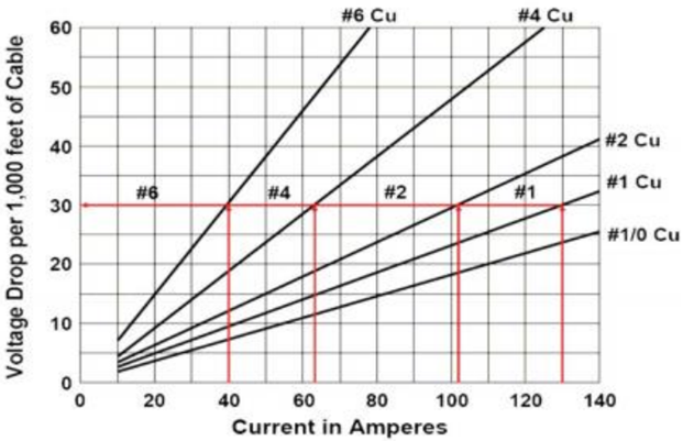
This article features the symptoms of voltage drop basic procedures and grounding tests to keep you safe. How to calculate voltage drop across multiple wire gauges. Impedance Z 10 Omega Putting values in the voltage drop formula we get.
The - orientation of a voltage drop is called the polarity. Voltage across an uncharged. A voltage loss of 03 volts or less is common for a switch.
Formula for voltage drop across capacitor. There is always a distance between your transformer and the fixtures. As tempting as it may be to use a voltage divider to step down say a 12V power supply to 5V voltage dividers should not be used to supply power to a load.
Note that a milliamp is onethousandth 0- 001 of an. Solved Example on Voltage Drop Example 1. Because most computer circuits operate way down in the milliamp range they dont tolerate voltage drop as well as other circuits do.
Here Im going to write the formulae of voltage drop across a capacitor is various stages like. 010V at a ground. But in the case of a practical real-world voltage source some amount of voltage drop occurs.
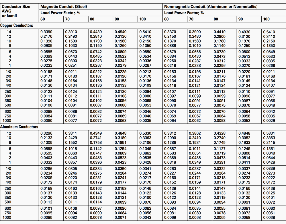
The ALLDATA Tech-Assist Team. SIZE OF COPPER CONDUCTOR. In the parallel circuit diagram the voltage drop can be calculated using Ohms Law and the equation of total resistance.
030V across a switch. When the capacitor is fully charged. If that power.
This equates to a total range of 253V to 205V. The track is the wire the cart is the current flow the rough parts of the track are resistors and you pedaling the bicycle are the battery. Voltage Drop Across Resistors in.
So the voltage drop is 90 V. Assuming you intend to ask what is the voltage drop across the 60 ohm resistor the answer is 120v. The current through the circuit was 001961textA.
This range takes into account the voltage range allowed at the point of supply and the additional 5 voltage drop in the installation. For a resistor R as in the Fig. This formula can help you determine voltage drop across a circuit as well as the size wire gauge you will need for your circuit based on the maximum desired voltage drop.
1 below the voltage drop from pointa to b V Vab VaVb is given by V IR. Build circuits with batteries resistors ideal and non-Ohmic light bulbs fuses and switches. A resistor which obeys Ohms Law is said to be ohmic.
If the fixtures are far from the transformer the voltage drop will increase. Assume a circuit is subject to the following conditions. The voltage drop in parallel circuit is constant throughout the parallel circuit branches.
Resistors in parallel have the same numerical voltage drop because they are connected between the same two nodes. Determine if everyday objects are conductors or insulators and take measurements with an ammeter and voltmeter. In an ideal voltage source the voltage drop across the source is zero.
How to Select Wire Size. This voltage drop increases as the current increases. On the other hand in a.
Use a thicker 12 or 10-gauge wire to limit issues with voltage drop. Voltage Current and Resistance Worksheet. We can now calculate the power loss in one wire.
The voltage drop across the electrical load is proportional to the power available to be converted in that load to some other useful form of energy. The VI characteristics of ideal and actual DC voltage source are as shown in the below figure. Read the followings for these.
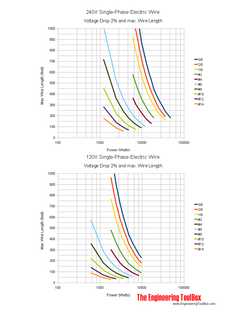
Each parallel wire has the same voltage as the entire circuit. The NEC recommends a maximum voltage drop of 5 across feeders and branch circuits and 3 across the branch circuit alone. Related to the voltage drop if you need power across distances longer than 50 feet youll probably want a copper wire.
We say that the voltage across each resistor is the same. This is the full range of voltage an appliance should receive and an electrician should measure it in an installation under normal conditions. Find the voltage drop across the circuit.
Through a circuit a current of 9A flows through that carries a resistance of 10 Omega. The voltage drop of the copper wire conductor can be found out as follows. TextP_textwire 0049025cdot001961 000096138textW 096138textmW.
Any current that the load requires is also going to have to run through R 1. To go beyond 50 feet youll likely need a higher gauge copper wire. The voltage drop over one piece of wire is as calculated above 0049025textV.
For devices that draw less current than a starter motor you can find published tables that claim there should be no measurable voltage drop at all between a wire and its crimped-on connector no more than 100mV 01 volts between a connector and the terminal its pushed onto and no more than 300mV 03 volts across a switch. Meanwhile a 16-gauge wire is about 3153 feet long and a thicker 12-gauge reaches up to 10688. The voltage drop across an electrical load is proportional to the power available to be converted in that load to some other useful form of energy.
During discharging of the capacitor. 020V across a wire or cable. The upper terminal of R 1 and the upper terminal of R 2 are connected together by an idealized wire that has zero resistance.
2
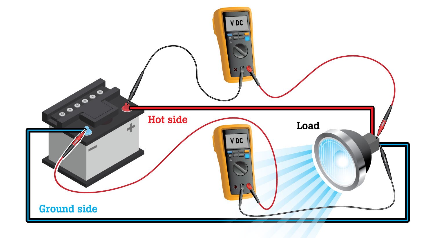
Diagnosing Voltage Drops Electrical Automotive Troubleshooting Fluke
Power Losses In Cables Production Technology
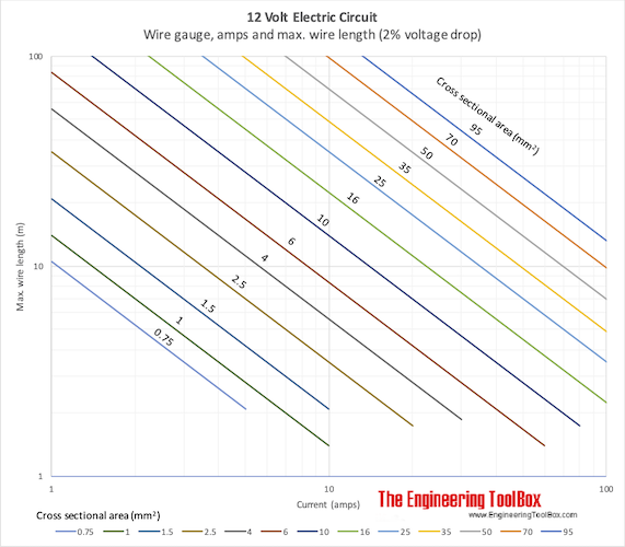
12 Volt Maximum Wire Length Vs Current

Voltage Drop Explained Electricity Forum
Voltage Drop Calculation Methods With Examples Explained In Details Eep
Voltage Drops And Troubleshooting Locksmith Ledger
Electric Wire Maximum Length With 240 Volts Single Phase Power
Voltage Drop Calculation Methods With Examples Explained In Details Eep

Voltage Drop Calculation For Single Phase And Three Phase Systems Electrical Axis
Voltage Drops And Troubleshooting Locksmith Ledger
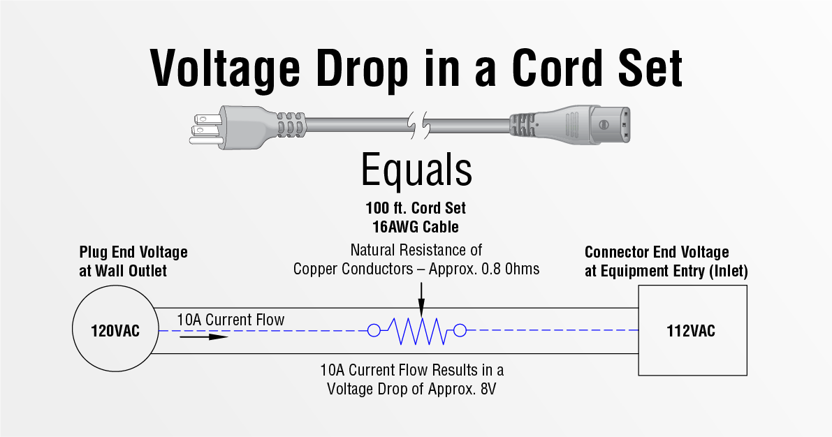
The Value Of Calculating Voltage Drop Infopower Interpower

8 Loss And Voltage Drop Across The Cable For 48 V Dc Download Table

How To Calculate Voltage Drop In Electrical Cable Cable Sizing Calculations Part 2 Youtube

Determining Voltage Drop Lectromec

Voltage Drop In Cables Download Table

Determining Voltage Drop Lectromec